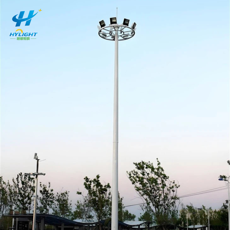
A high mast light pole with a lowering carriage is purchased so luminaires can be serviced near ground level. That benefit depends on a complete mechanical and electrical load path: winch, drive or power tool, torque-limiting arrangement, drum, ropes and terminations, sheaves, headframe, carriage, guides, latches or a non-latching holding system, trailing cable, connectors, controls, and operating procedure.
Checking the mast shaft and galvanizing does not prove that this mechanism will work safely after installation. Nor does one unloaded up-and-down demonstration prove that the supplied system matches the approved load, drawings, and maintenance plan. Municipal owners, ports, airports, highway agencies, stadiums, EPC contractors, and industrial operators need a configuration-specific factory acceptance test and handover dossier.
This guide turns the raising/lowering package into practical review, witness, inspection, and record points. It is not a substitute for the contract standard, manufacturer procedure, qualified engineering, or a site-specific safety plan.
GEO Summary
- State the system architecture first: top-latching, another defined latching arrangement, or non-latching/self-sustaining. Each design needs an architecture-specific safety case and acceptance sequence.
- Freeze the real operating load: carriage, luminaires, brackets, control gear, junction boxes, cables, connectors, lightning equipment, cameras or other approved devices, plus the intended operating tool and configuration.
- Approve signed working drawings, calculations, component schedules, rope and material certificates, welding/fabrication records, wiring, operating logic, and inspection/test plan before the FAT.
- Verify the winch, drive, torque limiter, drum and rope lay, rope identity/condition/terminations, sheaves and guards, headframe, carriage level, guides, latching or holding function, trailing cable, controls, limits, earthing, labels, and service access.
- Define the FAT load, number of full cycles, speed or time expectations, acceptance criteria, inspection after each cycle, abnormal-stop demonstrations, retest rule, and records in the contract. Do not invent these values at the factory.
- A factory test does not replace receiving inspection, installation checks, site proof cycles, commissioning, or maintenance training. Close each stage with signed records and as-built configuration data.
- For a project-specific proposal, send Henlyte the mast height, site/wind criteria, luminaire schedule and total carriage load, carriage arrangement, lowering architecture, supply, operating method, quantity, destination, and required witness/approval plan.
The Short Answer: What Should a High Mast FAT Prove?
The FAT should prove that the approved, traceable mechanism can support, raise, hold or latch as designed, unlatch where applicable, lower, stop, and be serviced in a controlled manner using the offered load and operating equipment. It should also prove that ropes, cables, connectors, guards, labels, and records remain correct after the specified test sequence.
A useful FAT closes five questions:
- Is this the approved system? Drawings, part numbers, materials, load, and revisions match.
- Is the load path complete? Carriage-to-rope-to-sheave-to-drum-to-winch-to-support structure is visible and traceable.
- Does the operating logic work? Raise, stop, hold/latch, release, lower, limits, torque protection, controls, and power isolation behave as designed.
- Does the system remain healthy? Ropes, terminations, drum lay, sheaves, carriage, cable, fasteners, and alignment show no unacceptable change after each cycle.
- Can the owner operate and maintain it? Tools, instructions, spare parts, inspection intervals, training, and as-built records are handed over.
Henlyte’s high mast light pole category can establish the product direction. The FAT schedule must then identify the exact lowering system and offered configuration.
Identify the Architecture Before Writing the Test
High mast lowering systems do not all support the carriage in the same way. Some use latches at the mast head so the raised carriage transfers load to defined support points. Other systems use a self-sustaining winch or another engineered non-latching arrangement that keeps the suspension system in its designed state. The mechanism, load condition, inspection access, release sequence, and failure modes differ.
The supplier should declare:
- the system type and design principle;
- the number and arrangement of suspension ropes;
- whether ropes remain loaded or unload after latching;
- how the carriage is centered and prevented from rotating;
- how the raised carriage is supported;
- how latching status is indicated and verified, if latches are used;
- how motion is controlled and stopped;
- how an unintended descent is prevented;
- whether the drive is internal, external, portable, or permanently installed;
- how torque limiting, braking, self-sustaining gearing, interlocks, and limits work;
- how the trailing power/control cable is managed independently from suspension ropes;
- what the operator must inspect before, during, and after movement.
Do not paste a latch-engagement test into a non-latching design or accept a non-latching claim without evidence for its holding method. Approval begins with the offered architecture.
The Henlyte high mast with raising/lowering system page can be used to start an application discussion, while the final drawing and method statement must define the actual system supplied.
Freeze the Operating Load and Configuration
The FAT load should represent the contract-defined condition, not an arbitrary empty ring. Prepare a mass and configuration schedule for:
- carriage or lantern ring and all structural brackets;
- each luminaire, mounting bracket, fastener, aiming accessory, and safety restraint;
- remote or local drivers/control gear and their enclosures;
- junction boxes, distribution equipment, plugs, and connectors;
- trailing electrical cable and any signal or communication cable;
- lightning-protection equipment mounted on the carriage or headframe;
- cameras, antennas, sensors, beacons, signs, or other approved attachments;
- cable loops and service allowances that move with the carriage;
- approved future allowance, only if it is included in the design basis.
Record total suspended mass, center-of-gravity assumptions, number and position of luminaires, ring diameter, wind area used in structural design, and winch/rope selection. If the FAT uses calibrated substitute weights instead of the final luminaires, document the arrangement and show that it represents the agreed mass and load distribution without creating an unrealistic center of gravity.
The mast, headframe, winch, rope set, carriage, and drive should share a project and pole identification. A test on a generic workshop rig is useful development evidence but is not automatically acceptance evidence for a different supplied configuration.
Approve the Document Dossier Before Witnessing Motion
The witness team should receive a controlled dossier early enough to review it before travel or a remote FAT.
| Document | What it should establish |
|---|---|
| Approved general arrangement | Mast/pole ID, height, sections, headframe, carriage, luminaires, door, winch, and access |
| Raising/lowering working drawing | Rope paths, sheaves, terminations, drum, guides, latch/holding arrangement, cable path, clearances |
| Design and checking record | Applicable contract/code basis, loads, component capacities, safety factors or utilization as required |
| Component schedule | Manufacturer, model, rating, material, quantity, revision, and project mapping |
| Rope and termination dossier | Rope construction/material/diameter/length/batch, certificate, breaking strength basis, termination method and inspection |
| Winch/drive dossier | Capacity, ratio, drum, torque limiter/brake or self-sustaining principle, motor/tool, controls, lubrication |
| Fabrication and coating records | Material traceability, welding procedures/qualifications, inspections, galvanizing/coating evidence |
| Electrical package | Single-line/wiring diagrams, trailing cable, plugs, junction boxes, controls, earthing, isolation, limits |
| FAT procedure and ITP | Setup, load, instruments, steps, acceptance criteria, hold/witness/review points, retest rule |
| Operation and maintenance draft | Safe operating sequence, inspections, lubrication, rope criteria, spares, troubleshooting, rescue/recovery boundary |
If the procedure does not match the approved drawing or architecture, stop the document review before the physical test. The factory floor is not the place to invent acceptance criteria.
Build an Inspection and Test Plan With Named Roles
Use hold, witness, review, and surveillance points appropriate to the contract. A simple structure is:
| Stage | Example control point | Typical record |
|---|---|---|
| Material and components | Rope, winch, sheaves, shafts, fasteners, electrical cable and enclosures identified | Certificates and receiving inspection |
| Fabrication | Critical dimensions, welds, headframe and carriage assembly, coatings | Inspection report, NDT/coating records where specified |
| Pre-FAT review | Approved revisions, calibrated instruments, load arrangement, risk controls | Readiness checklist and release |
| Static inspection | Complete mechanism inspected before operation | Dimensional/visual checklist and photographs |
| Functional FAT | Defined raise/hold-or-latch/release/lower cycles and protective functions | Cycle log, readings, video where permitted |
| Post-cycle inspection | Rope, drum, sheaves, carriage, latches, cable, fasteners, leaks, damage | Inspection after each or defined cycle |
| Punch-list closeout | Deficiencies corrected and affected tests repeated | Nonconformance and retest record |
| Packing release | Parts list, pole numbering, preservation and documents complete | Packing inspection and release note |
Name the supplier test lead, safety controller, operator, instrument recorder, owner/engineer witness, and person authorized to stop the test. Everyone should know that an unusual noise, rope crossover, slack condition, binding, unexpected movement, cable snag, oil leak, loose component, or control anomaly requires a controlled stop and investigation under the approved procedure.
Prepare a Safe and Representative FAT Setup
The FAT area should be controlled, barricaded, and suitable for the full travel or approved representative rig. The supplier should issue a task risk assessment and method statement addressing suspended loads, moving parts, pinch/crush zones, electrical supply, test weights, temporary supports, communication, emergency isolation, and recovery.
Confirm:
- the test fixture or mast section is designed and secured for the test;
- the offered headframe, carriage, winch, ropes, cables, controls, and drive are installed in the approved orientation;
- calibrated or verified measuring devices are available for the specified readings;
- the test load and distribution are documented;
- guards, covers, remote control lead, and exclusion distances match the procedure;
- lighting and camera positions allow inspection without entering the hazard zone;
- power voltage/frequency and protective earthing match the test plan;
- lubrication, oil level, fasteners, rope routing, and cable management have been checked;
- an agreed stop and recovery process is available before motion begins.
Remote witnessing can supplement records, but the camera should show identifying labels, load arrangement, controls, complete travel, latch or holding indicators, rope/drum behavior where safe, and post-test inspection. A short edited video is not a substitute for signed data and traceability.
Inspect the Winch, Drive, and Torque Protection
Record the winch manufacturer/model, rated capacity, serial or batch, gear ratio, drum details, mounting frame, lubricant, and direction of operation. Confirm that mounting, fasteners, alignment, guarding, and access match the drawing. The winch should be removable or serviceable by the method promised in the maintenance manual.
For a motorized or portable drive, verify voltage, power, connector, mounting/coupling, direction, controls, cable length, and manual or recovery provisions defined by the manufacturer. A remote control should return or stop as designed when released; the exact logic must follow the approved system.
Where a torque limiter is part of the safety and overload strategy, require a documented setting method, calibration or verification basis, tamper control, acceptance range, and test result. The FAT should demonstrate its intended protective function using the manufacturer-approved procedure. Do not create an unsafe obstruction or overload outside that procedure.
Where braking or self-sustaining gearing is the holding principle, the design and FAT should demonstrate the required holding and stopping behavior in the contract-defined condition. Do not assume a gear ratio alone proves the full system behavior.
Inspect seals, oil leakage, unusual heat, noise, vibration, backlash, drum condition, and fastener movement after the cycle sequence. Record observations rather than relying on “satisfactory” alone.
Verify Wire Ropes, Terminations, Drum Lay, and Sheaves
Each rope should be traceable to the approved construction, material, diameter, length, batch, and certificate. The design dossier should state the required minimum breaking strength or component capacity and the contract calculation should show the load/utilization basis. Do not apply a factor from an unrelated specification without confirming the governing standard and architecture.
Before operation, inspect for shipping or assembly damage, corrosion, contamination, kinks, flattening, birdcaging, broken wires, incorrect lay, crossed ropes, loose hardware, and unequal tension. Verify that end terminations, thimbles, sockets, swages, grips, or other approved fittings match the drawing and manufacturer procedure. Record orientation, quantity, spacing, torque, proof/testing evidence, or dimensional checks required by that method.
At the drum, confirm:
- correct anchorage and remaining wraps at the defined travel limit;
- grooving or winding arrangement suited to the rope;
- orderly lay without crossover, crushing, or climbing;
- alignment between drum and lead path;
- guards and clearances;
- no contact with sharp edges, fasteners, wiring, or the mast door;
- accessible inspection points.
At the headframe, verify sheave diameter/type, groove compatibility, bearings/bushes, shafts, retainers, separators, guards, alignment, and free rotation. The suspension ropes and trailing electrical cable should follow their intended independent paths and should not twist or abrade each other.
After each specified cycle or inspection interval, check for new marks, strand disturbance, uneven tension, drum migration, sheave binding, termination movement, or cable entanglement. Photograph the starting and final condition from repeatable positions.
Inspect the Headframe, Carriage, Guides, and Level
The headframe should match the mast interface, orientation, and component layout. Verify structural members, plates, welds, fasteners, sheave supports, lightning equipment, cable guides, covers, and drainage. Check that shipment or assembly cannot reverse a component that has a required direction.
The carriage should match its approved diameter, segments/joints, luminaire brackets, junction boxes, cable supports, guide arms or rollers, buffers, centering devices, and latch interfaces. Record the final luminaire positions and aiming references or the substitute-load positions used at FAT.
During travel, observe whether the carriage remains acceptably level and centered under the contract criteria. Ropes should share the load as designed; guides should not bind; brackets and cables should clear the mast; and the carriage should approach the headframe without impact or uncontrolled rotation.
At the lowered service position, verify that the owner can access luminaires and electrical components without resting the ring on cables or creating an unstable work condition. The manual should define any stands, supports, or ground-level restraints required before maintenance begins.
The high mast street light pole and an outdoor galvanized 25 m high mast direction illustrate why mast height and application must be tied to a specific carriage load and mechanism rather than a generic FAT.
Test Latching and Non-Latching Systems Correctly
For a latching system, the procedure should define how the carriage enters the latch zone, how each latch engages, how successful engagement is indicated or physically verified, how the load transfers, how rope condition changes, and how the carriage is released for lowering. Acceptance should cover all latch points, level, load transfer, repeatability, and the absence of damaging impact or partial engagement.
The witness should not infer complete engagement from motor sound or carriage height. Use the manufacturer’s approved indicators and inspection method. If one latch fails to engage, stop, investigate, correct the cause, and repeat the affected test sequence under the agreed retest rule.
For a non-latching or self-sustaining system, record the designed holding method, continuous rope condition, winch behavior, stopping, load retention, and any secondary protection. The acceptance test should demonstrate those functions without pretending a missing latch is a defect.
The maintenance plan should reflect the architecture. Latches at height need their own inspection, cleaning, wear, alignment, and corrosion controls. A non-latching winch/rope system needs inspection and maintenance appropriate to its continuous load path. Neither architecture is maintenance-free.
Verify the Trailing Cable and Electrical System
The moving electrical cable should be identified by type, conductor/core count, voltage, length, flexibility, environmental rating, and project circuit. Check terminations, plugs/sockets, junction boxes, strain relief, earthing continuity, separation from suspension ropes, bend control, and travel without snagging, twisting, crushing, or abrasion.
Where the system allows the carriage to be powered at ground level, verify the intended connection and isolation arrangement using the approved procedure. The operator should not improvise temporary leads or energize exposed work.
Test controls, direction indication, stop function, limits or position logic, remote lead, emergency isolation, and any interlocks required by the design. Record supply conditions and results. Confirm that luminaire circuits, controls, and auxiliary equipment remain correctly connected after the motion sequence.
The final proposal should also coordinate the high mast with the selected LED flood light category, because luminaire quantity, mass, wind area, brackets, drivers, cables, and aiming affect the carriage and structural schedule.
Define Full Functional Cycles and Retest Rules
A complete cycle should use the sequence applicable to the architecture: controlled raise, approach, latch/load transfer where used or defined raised hold for non-latching systems, release/unlatch where used, controlled lower, and stop at the service position. Inspect defined components at the points stated in the ITP.
The purchaser’s specification should state:
- load and load distribution;
- operating equipment and supply;
- number of complete cycles;
- allowable speed/time range if relevant;
- level/alignment criteria;
- latch or holding acceptance;
- torque-limiter/protective-function checks;
- cable and rope inspection frequency;
- allowable temperature, noise, leakage, movement, or wear criteria where measurable;
- data, photographs, video, and signatures required;
- stop, nonconformance, correction, and full or partial retest rule.
One public installation specification uses repeated full raise/latch/unlatch/lower sequences and requires inspection after each sequence, with the full process repeated after a corrected deficiency. That is a useful evidence principle, not a universal number for every factory test. Put the actual project cycle requirement in the contract.
Do not continue cycling through an unexplained fault to “complete the count.” A completed unsafe or damaging cycle is not acceptance.
Demonstrate Controlled Stops and Defined Protective Functions
The FAT should demonstrate normal stopping at intermediate and final positions, control release behavior, power isolation, direction control, and protective functions specified by the manufacturer and contract. If loss of power, torque limitation, limit action, or another abnormal scenario is part of the approved procedure, perform it only with the supplier’s engineered method, controlled load, exclusion zone, and recovery plan.
Acceptance is not a dramatic emergency demonstration. The goal is to confirm predictable behavior without placing people beneath a suspended load or intentionally damaging the mechanism. Record the initial condition, test trigger, response, final safe state, reset/recovery action, and post-test inspection.
Any function that cannot be safely demonstrated at FAT should be addressed through design evidence, component certification, a purpose-built test, or another agreed verification method – not silently marked passed.
Close Deficiencies With Traceable Retesting
Every observation should receive a unique number, description, photograph, severity, responsible party, due date, corrective action, and required verification. Examples include rope crossover, incorrect termination hardware, unmatched drawing revision, carriage tilt, latch non-engagement, cable rubbing, loose fastener, leaking winch, wrong control direction, missing label, or incomplete certificate.
The engineer or owner should decide whether a correction requires:
- visual/document closeout only;
- reinspection of the affected component;
- repetition of one function;
- repetition of the full cycle sequence;
- design review or calculation update;
- replacement of a component or batch;
- a new witnessed FAT.
Do not alter a rope termination, torque-limiter setting, latch, guard, control circuit, or structural component and then release the equipment without documenting the change and retest.
Protect Traceability During Packing and Shipping
A successful FAT can be undone when components are mixed between poles or damaged in transit. Pack the raising/lowering equipment as a complete identified set where practicable. The packing list should map headframe, carriage sections, winch, rope set, drive/tool, controls, cables, plugs, fasteners, guards, accessories, spares, manuals, and certificates to the pole/project ID.
Protect machined, threaded, electrical, rope, and coated surfaces from moisture, impact, contamination, and deformation. Restrain ropes and cables without tight bends or crushing. Mark lifting points, center of gravity, storage orientation, weather limits, and preservation/reinspection needs.
Photograph the final packed condition and seals. At site, inspect before and after unloading and record damage or missing items. A factory-passed component should be quarantined if shipment condition puts its acceptance in doubt.
Factory Acceptance Does Not Replace Site Proof
After foundation, mast, headframe, carriage, ropes, winch, cable, luminaires, and electrical system are installed, perform the contract-defined installation and commissioning checks. Verify mast/pole identity, section assembly, headframe orientation, rope routing, winch mounting, carriage load, cable path, grounding, supply, controls, lubrication, fasteners, access, and site safety zone.
Run the required site proof cycles with the actual installed configuration and inspect the mechanism as specified. Confirm carriage level, latch or holding function, rope/drum/sheave behavior, trailing cable, luminaire operation, aiming references, and ground-level service access. Correct a deficiency and repeat the required sequence rather than accepting “factory test passed” as a waiver.
The handover package should include signed factory and site records, as-built drawings, final component/serial schedule, certificates, punch-list closeout, commissioning settings, operation and maintenance manuals, inspection intervals, spare parts, special tools, training attendance, and warranty contacts.
Maintenance and Spare-Parts Handover
The owner needs a planned inspection regime for the entire mechanism. The manufacturer should define pre-operation checks, periodic inspection, lubrication, rope examination and discard criteria, termination checks, drum/sheave condition, winch oil and seals, torque-limiter verification, latch or holding-system inspection, cable/connector checks, corrosion repair, fastener checks, electrical tests, and records.
Provide project-specific spare and service information for:
- approved suspension and winch ropes with termination kits;
- sheaves, bearings/bushes, shafts, retainers, and guards;
- winch seals, lubricant, gears or approved service assemblies;
- torque limiter, brake, couplings, drive/tool, and controls;
- latch parts or architecture-specific holding-system components;
- trailing cable, plugs, sockets, strain relief, junction boxes, and fuses;
- carriage guides/rollers, buffers, fasteners, and brackets;
- door seals, locks, labels, coating-repair materials, and special tools.
State storage conditions, shelf life where applicable, authorized repair boundary, availability period, and obsolescence/substitution process. Provide an editable inspection form so the owner can build a service history by pole.
Red Flags in a High Mast Raising/Lowering Offer
- The supplier does not identify whether the system is latching or non-latching.
- The winch and rope are selected from mast height alone without a complete carriage load.
- The rope certificate, construction, batch, termination method, and design calculation cannot be mapped to the supplied pole.
- The FAT is one unloaded movement with no component inspection or recorded acceptance values.
- The torque limiter or holding function is described but has no approved verification method.
- The trailing cable shares an uncontrolled path with suspension ropes or lacks strain relief and ground-level connection details.
- The carriage reaches the top, but latch status or raised holding is inferred rather than demonstrated.
- A deficiency is adjusted during FAT without a nonconformance or retest record.
- The factory test uses a different winch, rope set, headframe, controller, or power tool from the delivered system.
- Packing lists do not map loose components to each pole.
- The service manual is generic and does not contain the delivered component models, settings, diagrams, or inspection intervals.
- Operators are expected to improvise recovery or work beneath a suspended carriage.
Image Suggestions
Use the existing Henlyte high mast image as the featured image with the alt text “high mast raising and lowering system FAT for winch, wire rope, headframe, carriage, and handover.” Add an original load-path diagram from carriage through suspension ropes, sheaves, headframe, drum, and winch, with the trailing electrical cable shown on a separate path. A second image can be a five-stage FAT storyboard: document/revision check, static component inspection, controlled full cycle, post-cycle rope and latch/holding inspection, and pole-numbered packing release. Show latching and non-latching architectures as separate examples and label dimensions/loads as project-specific.
FAQ
Is one unloaded high mast raising and lowering cycle enough for FAT?
Usually it is weak evidence. The contract should define a representative load, complete operating sequence, number of cycles, inspections, acceptance values, protective-function checks, and retest rule. The FAT must match the approved system and should be followed by site proof after installation.
What load should be used for a high mast lowering-system FAT?
Use the contract-defined load representing the offered carriage configuration: ring, luminaires, brackets, control gear, boxes, cables, connectors, approved accessories, and agreed allowance. If substitute weights are used, document their mass and distribution and show why they represent the accepted condition.
Do all high mast lowering systems need top latches?
No. Latching and non-latching/self-sustaining architectures exist. The supplier must identify the design principle and demonstrate its approved holding, stopping, rope, inspection, and maintenance strategy. Do not apply a latch test to a design that intentionally has no latch.
Which wire-rope records should be provided with a high mast?
Provide the approved rope construction, material, diameter, length, batch/heat or traceability reference, certificate and breaking-strength basis, design load/utilization record, termination drawing and inspection, installation identity, FAT observations, and final pole mapping required by the contract.
What happens if a fault occurs during the high mast FAT?
Stop the test in a controlled condition, record the fault, investigate and approve the corrective action, inspect affected components, and repeat the function or full sequence required by the ITP. Do not continue through an unexplained rope, winch, latch, cable, alignment, or control problem.
What must be handed over after high mast commissioning?
Handover should include approved as-built drawings, calculations and component schedules, material/rope/welding/coating records, factory and site test reports, nonconformance closeout, final serial/pole mapping, wiring and settings, operation and maintenance manuals, inspection forms, spares/tools, training records, and warranty contacts.
Inquiry CTA
Planning high mast lighting for a port, logistics yard, highway interchange, airport apron, industrial plant, stadium, railway yard, or large public area? Send Henlyte the site location, mast height, design criteria, luminaire layout and total carriage load, wind and corrosion conditions, lowering architecture preference, power/control arrangement, foundation interface, quantity, destination, FAT witness requirements, and handover schedule.
Use the Henlyte project inquiry form and include “high mast raising and lowering FAT” so the team can identify the required drawings, winch/rope/headframe data, inspection points, service package, and missing project inputs. For a wider pole program, review the Henlyte light pole category together with the high mast configuration.