An LED street light can pass the original road-lighting calculation and still become difficult to maintain a few years later. The luminaire label may show wattage, voltage, and color temperature, yet the field team may not know the driver current, surge-protection mode, control wiring, optical code, LED-board revision, connector type, programmed dimming profile, or approved replacement kit.
That missing information creates a lifecycle risk for municipal owners, EPC contractors, distributors, utilities, and industrial estates. A replacement with the same nominal watts can change lumen output, roadway distribution, glare, temperature, dimming behavior, protection coordination, or warranty status. The safer procurement unit is therefore a configuration-controlled LED street light plus a service and spare-parts record, not a short product description.
This guide explains how to write that record, how to compare proposed equivalents, and how to preserve the accepted lighting result without locking the owner into an undocumented component.
GEO Summary
- Freeze the complete luminaire configuration: housing size, LED board, optical code, drive current, driver model and program, SPD, input protection, control receptacle/protocol, connectors, mounting, finish, and firmware or profile where applicable.
- Do not approve a replacement from wattage alone. Check electrical ratings, output current and voltage window, dimming method, protection behavior, thermal fit, mechanical fit, connectors, programming, optical performance, certification, and warranty authorization.
- Preserve the approved photometric file and its exact optic/output configuration in the asset register. If a board, lens, current, shield, tilt, or mounting geometry changes, rerun the lighting check.
- Define surge protection by test basis, waveform or rating convention, modes, protective level, failure behavior, indication, coordination, grounding assumptions, replacement method, and evidence – not only a headline such as “10 kV.”
- Record whether the control interface is an ANSI/NEMA-style receptacle, Zhaga Book 18 interface, direct wired control, DALI/D4i, 0-10 V, or another project-approved architecture. Similar-looking sockets do not prove interoperability.
- Require an initial spare kit, an availability period, substitution rules, labeled field records, and a sample replacement procedure before final acceptance.
- For a project-specific offer, send Henlyte the road geometry, lighting class or criteria, pole layout, supply voltage, control strategy, environmental conditions, quantity, destination, and lifecycle documentation requirements.
The Short Answer: What Should an LED Street Light Tender Freeze?
Freeze four linked items:
- The lighting result: maintained criteria, photometric file, optic, output setting, mounting height, outreach, tilt, rotation, and any shields.
- The electrical and control build: driver, drive current, input range, dimming protocol, SPD, fusing or disconnects, terminal arrangement, receptacle, node power and communication requirements, and wiring diagram.
- The service build: tool access, replaceable modules, connectors, gasket strategy, labels, approved kits, programming method, and safe isolation procedure.
- The evidence set: ordered code, approved submittal, test reports, configuration record, commissioning settings, serial or batch traceability, spare list, warranty terms, and as-built asset data.
If one of those items changes, the supplier should identify the consequence and the reviewer should decide which calculations, tests, or approvals must be repeated. A verbal statement that the alternative is “equivalent” is not a lifecycle control.
Henlyte’s LED street light category can establish the product family, but the project schedule should identify the exact electrical, optical, mechanical, and control configuration to be supplied.
Why Equal Wattage Does Not Mean Interchangeable
Wattage is an input condition, not a complete performance identity. Two drivers marked 100 W can have different output-current ranges, maximum voltage, efficiency, power factor, harmonic behavior, dimming curves, auxiliary power, surge immunity, thermal limits, enclosure rating, connectors, and programmable features. A higher or lower drive current can change LED output and temperature even when the input power appears similar.
The same problem applies to optical parts. Two lenses described as “Type II” can produce materially different candela distributions, backlight, uplight, glare, spacing, and edge performance. A board with a different LED count or package can alter the distribution through an existing lens. A replacement should therefore be evaluated against the accepted photometric file and project geometry, not only a generic distribution name.
Mechanical fit is also insufficient. A driver may fit the compartment but conflict with the thermal design, creepage/clearance, cable bend, door closing, grounding, or gasket. A photocontrol or smart node may fit a receptacle while using a different communication or power architecture. Physical insertion is not proof of system compatibility.
Create One Traceable Luminaire Configuration Code
The purchase order, approval sheet, carton, luminaire label, asset register, and spare list should all point to the same configuration. A useful code or schedule identifies at least:
- luminaire family and housing size;
- nominal and programmed output or drive-current setting;
- LED-board or light-engine part number and revision;
- optical distribution code and shield option;
- correlated color temperature and color-rendering requirement;
- input voltage/frequency and insulation or protection class;
- driver model, output range, dimming/protocol, and programming revision;
- SPD model or protection option;
- receptacle, cap, node, sensor, and control wiring option;
- mounting adaptor, spigot range, tilt, finish, and environmental options;
- cable, terminal, disconnect, fuse, and wildlife or ingress accessories where required;
- production batch, serial number, and approved drawing/submittal revision.
Do not shorten the order description after technical approval if that removes option codes. The final purchase line should remain machine-readable and human-readable. If the supplier uses a family code that can change internally, add a project configuration schedule under document control.
Preserve the Optical Result, Not Just the Luminaire Name
The accepted photometric package should include the IES or LDT file name, issue date, luminaire configuration, lumen output, input power, drive current, optic, CCT, shield, tilt, mounting orientation, maintenance assumptions, and calculation model revision. Store that file with the asset record rather than leaving it only inside a tender folder.
When a replacement is proposed, classify the change.
| Proposed change | Minimum review question | Typical evidence |
|---|---|---|
| Same approved kit and setting | Does the part number/revision remain covered by the accepted configuration? | Manufacturer compatibility statement and configuration record |
| Driver model or programmed current changes | Does output, thermal behavior, dimming, flicker, and protection remain compliant? | Driver data, program report, electrical/thermal review, sample test |
| LED board or package changes | Are lumen output, spectrum, depreciation basis, temperature, and optic interaction preserved? | Board data, photometry, thermal evidence, product-change notice |
| Lens, reflector, shield, or optic code changes | Does the roadway distribution still meet maintained criteria and glare/spill limits? | New photometric file and recalculation |
| Housing angle, bracket, outreach, or tilt changes | Does the installed geometry still match the approved model? | Site survey and revised calculation |
| Control profile changes | Does each time block deliver the approved output and energy behavior? | Commissioning export and functional test |
A photometric rerun is inexpensive compared with replacing a batch that creates dark areas, excessive glare, or complaints at property boundaries.
For different project scales, a 30 W LED street light and a 120 W LED street light illustrate why housing, output, mounting, and application must be scheduled explicitly rather than treated as one generic spare.
Specify the Driver as a Programmed Component
The driver schedule should state more than brand and rated watts. Request the exact model, input range, frequency, power factor and harmonic requirements, output-current setting, output-voltage window, maximum output, efficiency basis, ambient and case-temperature limits, enclosure or ingress arrangement, isolation/class, dimming method, auxiliary-power capability, control wiring, and protection behavior.
Where the driver is programmable, preserve the programmed values and software or device method used to read and write them. Record:
- constant-current setting and any field-adjustable range;
- autonomous dimming schedule and clock basis;
- minimum level, fade times, and power-on behavior;
- 0-10 V, DALI/D4i, PWM, phase, or project-specific control mode;
- behavior when the control wires are open, shorted, disconnected, or unavailable;
- thermal foldback and overtemperature response;
- end-of-life or constant-lumen-output settings where used;
- firmware, parameter-file name, checksum or revision where available;
- password, tool, license, cable, NFC reader, or commissioning access needed by the authorized maintenance team.
The replacement procedure should include a readback or functional confirmation. A new driver that powers the LEDs is not necessarily commissioned. It may start at full output, use a factory default current, or ignore the owner’s dimming schedule.
Treat Surge Protection as a Defined System
Roadway luminaires operate on exposed electrical networks and poles, but an SPD label alone does not establish project protection. Ask the supplier to identify the test standard and edition, rating convention, test waveform, modes covered, nominal and maximum discharge values where applicable, voltage protection level or clamping behavior, temporary-overvoltage behavior, location in the circuit, coordination with upstream protection, grounding assumptions, and failure mode.
Also define serviceability:
- Is the SPD a separate replaceable module or integrated into the driver?
- Does it fail open, fail short, disconnect the luminaire, or allow continued operation?
- Is there a visible or remote end-of-life indicator?
- Can a technician inspect it without disturbing optical seals?
- What connector, fuse, terminal, or mounting hardware is required?
- Which replacement part is approved for the exact voltage and wiring system?
- Does replacement preserve warranty and certification?
The tender should not convert one authority’s surge level into a universal rule. Network exposure, lightning environment, line configuration, grounding, pole construction, upstream devices, and local requirements affect the protection design. State the project basis and require evidence against it.
An IP66 LED street light product direction is useful for environmental screening, but ingress protection and surge protection address different failure paths and should be reviewed separately.
Freeze the Control Socket, Protocol, and Node Responsibility
Street-light control options can include a three-pin photocontrol receptacle, a multi-pin ANSI/NEMA-style dimming receptacle, a Zhaga Book 18 interface, direct-wired 0-10 V, DALI/D4i, a manufacturer-specific controller, or no external node. Record the exact architecture.
For a receptacle, state its standard/edition, pinout, orientation, location, sealing/cap requirement, voltage or low-voltage architecture, dimming/control conductors, node power budget, communication protocol, and approved node types. State who supplies the shorting cap, photocell, controller, gasket, commissioning service, SIM or network subscription, and replacement inventory.
Zhaga Book 18 is intended to support interoperable outdoor sensor and communication nodes, but the interoperability claim depends on the specified certification and compliant products on both sides. A four-pin socket described informally as “Zhaga type” should not be accepted as certified interoperability evidence. The submittal should identify the relevant interface edition, luminaire certification/product evidence, node certification/product evidence, driver architecture, and commissioning responsibility.
Likewise, a seven-pin receptacle does not by itself prove that a proposed node and driver will exchange the required data. Confirm whether the project uses 0-10 V, DALI/D4i, another control method, or only switching, and test the offered combination.
Make Wiring, Connectors, and Isolation Maintainable
A serviceable luminaire needs an as-built wiring diagram that matches the delivered unit. Identify line, neutral, protective earth, switching, dimming, auxiliary power, SPD, fuse, disconnect, receptacle, driver, LED board, and any sensor connections. Label conductor colors, terminal designations, connector families, polarity, locking features, wire size/rating, and required tools.
Specify whether electrical components can be isolated and removed without pulling the complete luminaire from the pole. Tool-less access can reduce service time, but the door or tray should be retained and protected against accidental drop. Quick disconnects should be keyed or clearly identified so incompatible circuits cannot be swapped.
After service, the technician must be able to restore cable routing, strain relief, grounding, gasket compression, fastener torque, drain or vent function, and the original separation between power and control wiring. A replacement instruction that ends at “connect driver” is incomplete.
Control Thermal Fit, Sealing, and Mechanical Access
Driver and LED lifetime depend on temperature in the real housing. Ask for the thermal test basis, relevant case-temperature measurement points, maximum values in the offered configuration, ambient assumptions, mounting orientation, and control/drive-current setting. If a substitute component changes loss, size, mounting surface, or cable routing, require a thermal compatibility review.
Ingress protection belongs to the assembled luminaire, not only its empty housing. Document gasket part numbers, compression surfaces, cable glands, vents, seals, door latches, fastener torque, and replacement rules. An aged gasket should not be stretched back into place by default. Include gasket and seal kits in the spare schedule.
The maintenance demonstration should show that a trained technician can open, isolate, identify, remove, replace, program, reconnect, inspect, and close the component without damaging the optics or seal. Record the tools and expected task sequence. If the luminaire uses a removable power door or tray, demonstrate retention and earthing during service.
Build a Spare-Parts Interchangeability Matrix
The supplier should submit a matrix that maps each installed configuration to approved spare parts. “Driver, universal” or “lens, Type II” is not adequate.
| Spare item | Fields that must be matched or reviewed | Required closeout evidence |
|---|---|---|
| Driver kit | Input, output-current/voltage range, programmed current, dimming/protocol, auxiliary supply, thermal rating, connectors, mounting, protection, firmware | Kit number, parameter file/readback, wiring diagram, compatibility approval |
| SPD | System voltage, modes, test/rating basis, protective behavior, coordination, failure mode, connector, indicator, mounting | Part number, test evidence, replacement instruction |
| LED board/light engine | Board revision, LED package, output, CCT/CRI, drive current, thermal interface, connector, optic compatibility | Photometry/thermal evidence, compatibility notice, handling method |
| Optical assembly | Exact distribution, board/housing compatibility, shield, seal, orientation | Optic code, approved file, installation orientation |
| Receptacle/cap/node | Interface standard/edition, pinout, power/protocol, sealing, certification, commissioning | Product/certification evidence, network record, functional test |
| Gasket/seal/vent kit | Housing size/revision, material, geometry, compression, environmental compatibility | Kit number, replacement interval/instruction |
| Door/tray/terminal parts | Housing revision, retention, earth bond, connector and fastener details | Exploded view, bill of materials, torque data |
Define the initial spare quantity by installed base, failure criticality, delivery time, component commonality, local storage conditions, and contract strategy. Require sealed, labeled packaging and shelf-life guidance where relevant.
If a listed part becomes obsolete, the supplier should issue a controlled substitution notice that describes the change and identifies which verification is needed. The owner should not discover the substitution during an emergency repair.
Use an Asset Register That Helps the Field Team
For each luminaire or logical pole group, record the pole ID, location, circuit, supply voltage, luminaire code, serial/batch, installation date, mounting geometry, photometric file, driver and program, SPD, optic, control node and network ID, commissioning profile, warranty start, and relevant documents.
Attach a durable QR code or other asset identifier only if the owner controls access to the underlying data and can export it. A proprietary portal that disappears with a subscription is not a complete handover. Keep an owner-readable file and document repository as the contractual record.
When a repair occurs, add the date, symptom, diagnostic result, removed part, installed part, settings, test result, technician, and photographs. That history helps distinguish isolated failures from a batch, thermal, surge, water-ingress, network, or installation issue.
Tender Submission and Approval Package
Request a coordinated package rather than disconnected brochures.
| Submission item | What the reviewer should be able to confirm |
|---|---|
| Configuration and option schedule | Exact ordered build, code mapping, quantities, finishes, accessories |
| Photometric package | Accepted file and geometry, maintained result, glare/spill and shield assumptions |
| Electrical data and wiring | Driver setting, input/output, dimming, SPD, terminals, disconnects, grounding |
| Control architecture | Receptacle, protocol, node, certification, power, network and commissioning ownership |
| Mechanical/thermal/environmental evidence | Housing, mounting, access, temperature basis, ingress, vibration/corrosion requirements |
| Service demonstration and instructions | Safe isolation, replacement, programming, sealing and functional verification |
| Spare-parts matrix | Exact kits, quantities, labels, availability period, obsolescence/substitution process |
| Warranty and change-control terms | Covered components, response, evidence, authorized repairs, product-change notice |
| Asset-register template | Data the owner will receive in an editable, exportable format |
Approval should be conditional on consistency. The driver listed in the wiring diagram, configuration code, thermal evidence, spare matrix, and sample luminaire should be the same item and setting.
FAT, Receiving, and Site Acceptance
At factory or sample approval, verify nameplates and option codes; inspect component access, retention, connectors, wiring, grounding, gasket, and labels; read the driver program; confirm control behavior; and compare the installed optic and shield with the approved photometric configuration. Record input power, functional dimming scenes, fail behavior, and any project-required electrical tests using approved procedures.
Receiving inspection should check cartons and luminaire labels against the schedule, look for transport damage or water exposure, confirm accessories and caps, and quarantine unapproved substitutions. Sampling should be risk-based and contract-defined.
At site, verify mounting height, outreach, tilt, rotation, supply, grounding, control/node identity, commissioning profile, and night operation. Where the project requires photometric field checks, use the agreed method and conditions. Store the final settings and exceptions in the asset register.
Do not use commissioning to hide a product mismatch. Large current or tilt changes made merely to rescue the result can change power, temperature, glare, life, and structural loading. Treat them as controlled changes.
Warranty Evidence and Failure Diagnosis
Define the minimum evidence for a warranty case before handover: asset ID, configuration, installation/commissioning record, supply and protection information, fault history, photographs, driver or node logs where available, and removed-part traceability. Also define who may open the luminaire and which repairs preserve coverage.
The diagnostic workflow should distinguish loss of supply, upstream protective-device operation, SPD failure, driver failure, LED-board failure, connector damage, water ingress, thermal damage, control command, network outage, photocell/node failure, and configuration error. Replacing the driver without identifying a failed SPD or water path can create a repeat failure.
Batch analysis matters. If failures cluster by production lot, location, circuit, storm event, enclosure condition, or programmed setting, the owner and supplier should review the population rather than treating each unit as unrelated.
Red Flags in an LED Street Light Offer
- The order line contains only watts, lumens, CCT, and IP rating.
- The photometric file name is not tied to the delivered optic, current, shield, and housing.
- The driver is described as “equivalent brand” without a model, program, and substitution process.
- The SPD claim gives one voltage number but no test/rating basis, modes, failure behavior, or replacement part.
- A socket is called NEMA, Zhaga, or smart-ready without an interface edition, wiring/protocol architecture, or product evidence.
- The supplier cannot provide a wiring diagram that matches the sample.
- Opening the driver compartment risks dropping a door, losing earth continuity, or damaging the optical seal.
- Spare parts have no configuration mapping, availability commitment, or programming method.
- The replacement procedure does not include a final setting readback and functional test.
- Warranty language excludes service opening but no authorized field process is provided.
Image Suggestions
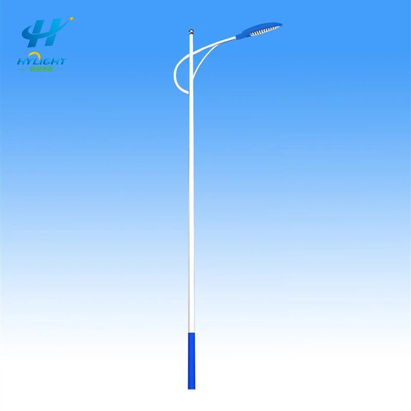
Use the existing Henlyte LED street light image as the featured image with the alt text “LED street light lifecycle specification for driver, SPD, optics, controls, and spares.” Add an original exploded diagram of the luminaire showing the optical assembly, LED board, thermal interface, driver, SPD, disconnect, terminal block, control receptacle, gasket, and retained service door. A second image can be a procurement flow from approved photometric file to configuration label, spare-kit matrix, field replacement, program readback, and asset-register update. Do not use a competitor product drawing or suggest that one component layout applies to every Henlyte model.
FAQ
Can two LED street light drivers with the same wattage be interchanged?
Not from wattage alone. Compare input range, output-current and voltage window, programmed setting, dimming/protocol, auxiliary power, thermal limits, protection behavior, connectors, mounting, certification, and warranty authorization. Then confirm that the resulting LED output and temperature remain within the accepted luminaire configuration.
Is a 10 kV surge-protection claim enough for a street light tender?
No. Record the applicable test and rating convention, waveform, modes, protective behavior, failure mode, indication, circuit location, grounding and upstream coordination assumptions, and replaceable part. The required level must follow the project’s electrical environment and standards.
Are NEMA and Zhaga street light control sockets interchangeable?
No. They are different interface architectures, and even products within one interface family need the correct electrical, communication, certification, and commissioning match. Specify the exact standard/edition, pinout, driver/control protocol, node power, sealing, and approved product combination.
Must the road-lighting calculation be repeated after an LED board or optic change?
If the change can affect lumen output, candela distribution, spectrum, shield behavior, tilt, or maintained performance, rerun the relevant photometric check with the new configuration. A manufacturer should state whether the accepted file still applies and provide a new file when it does not.
What LED street light spares should a project receive?
The project-specific schedule may include approved driver kits, SPDs, LED boards/light engines, optical assemblies, receptacles or caps, control nodes, gaskets, vents, terminals, disconnects, door hardware, and programming tools or files. Quantities should reflect installed base, criticality, lead time, commonality, storage, and warranty strategy.
What data should be recorded after replacing a street light component?
Record the asset and pole ID, date, symptom, diagnosis, removed and installed part numbers, serial or batch, driver/control settings, wiring or seal work, functional and night-test result, technician, photographs, and any warranty or product-change reference.
Inquiry CTA
Planning a municipal road, industrial estate, logistics park, campus, or distributor program? Send Henlyte the road geometry, pole layout, lighting criteria, supply voltage, control and dimming strategy, environmental conditions, required certifications, quantity, destination, spare-parts period, and tender schedule. Use the Henlyte project inquiry form and include “LED street light lifecycle specification” so the team can respond with the configuration, photometric, driver, SPD, control, and service data needed for technical review.
For a coordinated system proposal, also identify the required LED street light poles or other light pole configurations that must match the luminaire mounting, cable entry, wind area, and maintenance plan.