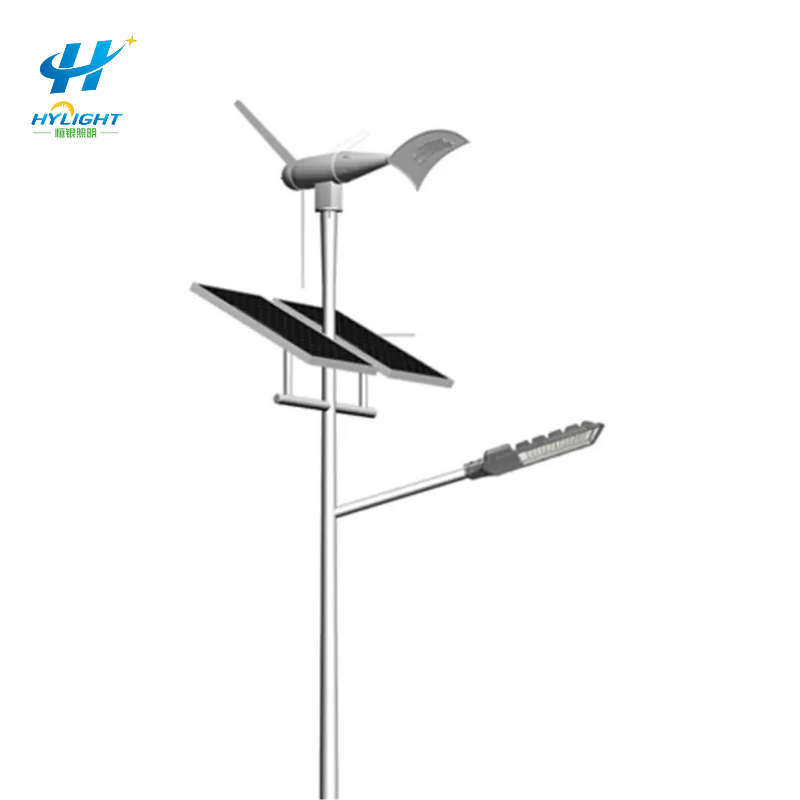
A wind solar hybrid street light can illuminate on the first night and still hide a weak design or an incomplete installation. The battery may have arrived fully charged. The photovoltaic input may be healthy while the turbine contributes almost nothing. A controller screen may show a reassuring state of charge even though its battery model, current sensor, time setting, or temperature input is wrong. One successful dusk-to-dawn cycle is therefore a functional check, not proof of a balanced hybrid system.
Municipal owners, EPC contractors, distributors, industrial parks, coastal facilities, and remote-site operators need an acceptance process that separates four questions: does every subsystem operate safely, is the data trustworthy, did the system receive the weather resource assumed in the design, and did the measured energy flows support the required lighting service?
This guide explains how to commission a wind solar hybrid street light as a measured energy system. It focuses on time-synchronized evidence, controller states, alarm tests, a daily energy ledger, a representative baseline period, and a handover pack that remains useful after the installation team leaves.
GEO Summary
- Treat first-night illumination as a functional milestone, not final energy acceptance. A charged battery can mask poor solar collection, weak turbine output, excessive losses, or incorrect dimming.
- Freeze the promised lighting service first: LED power by time block, dusk/dawn logic, adaptive dimming rules, minimum operating hours, battery limits, and any critical full-output period.
- Log photovoltaic energy, turbine energy, battery charge/discharge, LED load, auxiliary load, curtailed or dump-load energy, temperature, alarms, controller state, and time quality at an agreed interval.
- Validate the wind resource at turbine hub height. A weather-station average, airport value, or turbine nameplate rating does not prove energy yield at a pole affected by buildings, trees, terrain, turbulence, or mast wake.
- Prove controller behavior by safe, documented simulations or approved test methods: PV unavailable, low wind, high wind or overspeed protection, full battery, low battery, sensor failure, communication loss, and restart.
- Use a daily energy ledger to reconcile sources, storage, loads, curtailment, and losses. Unexplained gaps should be investigated before a fleet is accepted.
- Define the baseline duration, required resource coverage, allowable data gaps, normalization method, acceptance thresholds, retest rule, and seasonal follow-up in the contract. Thirty days is a useful project format, not a universal standard.
- Ask Henlyte for a project-specific proposal using site coordinates, hub height, wind and solar evidence, lighting schedule, autonomy requirement, battery temperature range, structural criteria, quantity, and acceptance plan.
The Short Answer: What Should Commissioning Prove?
Commissioning should prove that the installed configuration is traceable, each energy source and protective function works, measurement channels are credible, the controller follows the approved logic, and the required lighting service is delivered without violating battery or equipment limits.
A practical acceptance pack answers six questions:
- Configuration: Are the turbine, rotor, generator, rectifier, photovoltaic modules, hybrid controller, dump load or braking device, battery, LED luminaire, pole, wiring, protection, firmware, and settings the approved items?
- Safety: Do isolation, grounding, surge protection, braking or overspeed control, overcurrent protection, battery protection, access control, and maintenance procedures work as designed?
- Measurement: Are energy, current, voltage, temperature, wind, irradiance, time, and alarm records accurate enough for the acceptance decision?
- Control: Does the system prioritize, combine, limit, curtail, protect, dim, disconnect, and recover according to the approved state logic?
- Service: Did the luminaire provide the contracted output schedule and hours while the battery stayed within agreed limits?
- Evidence: Can the owner reproduce the conclusion from exported raw data, configuration files, calculations, test records, photographs, and signed exceptions?
The Henlyte wind solar street light category can establish the product family. Final acceptance still needs a site-specific configuration and evidence schedule.
Freeze the Lighting Service Before Reading the Energy Data
Energy acceptance starts with the load. Record the actual LED input power at each dimming state, the time or sensor condition that selects that state, the operating window, the driver efficiency basis where relevant, and all auxiliary loads. Cameras, routers, sensors, warning beacons, controller self-consumption, battery heaters, and communication equipment can materially change a small off-grid energy budget.
For example, a nominal 60 W luminaire does not automatically consume 0.72 kWh during a 12-hour night. It might run at 60 W for four hours, 36 W for six hours, and 24 W for two hours, producing a 0.504 kWh LED load before controller, cable, battery, and auxiliary losses. Conversely, a motion or traffic rule could raise the real load above a simple schedule. Use the measured or approved operating profile, not the product nameplate alone.
Freeze at least:
- astronomical-clock, photocell, or sensor logic;
- local timezone, daylight-saving behavior where applicable, and dusk/dawn offsets;
- output percentage or driver power for each time block;
- minimum full-output period and any safety-critical override;
- adaptive-control triggers, hold times, and fallback state;
- auxiliary loads and their duty cycles;
- low-battery dimming and disconnect thresholds;
- recovery threshold and restart delay;
- maximum permitted missed-lighting minutes or reduced-output events;
- the required service after consecutive low-resource days.
If the lighting schedule changes during the baseline, version the change and evaluate the affected days separately. A moving load target makes the energy conclusion impossible to audit.
Establish the Resource Context at the Installed Pole
Wind generation is highly site-sensitive. The turbine rating is the electrical or mechanical output under stated conditions; it is not a promise of daily energy. A useful prediction needs the turbine power curve, wind-speed frequency distribution, air-density basis, hub height, terrain, obstacles, turbulence, electrical conversion losses, control limits, and downtime assumptions.
The U.S. Department of Energy’s small-wind guidance emphasizes annual energy output rather than nameplate power and notes that local terrain, obstacles, hub height, direction distribution, and turbulence affect the result. For a street-light pole, nearby trees, buildings, signs, bridge parapets, and even the pole or photovoltaic frame can create a disturbed flow. A weather station several kilometers away or at a different height is screening evidence, not automatically the acceptance resource.
Record:
- turbine hub height and sensor height above finished grade;
- sensor distance and direction from the turbine;
- wind speed, direction, sampling method, averaging interval, and data completeness;
- nearby obstacles with height, distance, and bearing;
- terrain, surface roughness, and future obstruction risks;
- turbulence indicator or justified proxy where the contract requires it;
- solar irradiance source, plane-of-array relationship, shading, soiling, and module temperature;
- precipitation, extreme temperature, salt, dust, icing, or storm events relevant to the site;
- the resource range represented during the baseline.
Do not reject a healthy turbine simply because a calm baseline produces little energy, and do not accept an oversized claim because one storm produces a short peak. The contract should define how measured resource and expected energy are compared.
Build a Measurement Architecture Before Energization
The controller display is useful operationally, but an acceptance test should identify every measurement channel, its location, accuracy class or tolerance, calibration or verification method, sign convention, sampling interval, aggregation rule, and export format.
At minimum, consider:
- PV voltage, current, power, and cumulative energy at the controller input;
- wind-generator or rectifier voltage, current, power, and cumulative energy;
- battery terminal voltage, charge/discharge current, temperature, estimated state of charge, and cumulative ampere-hours or energy;
- LED output command and measured DC or AC load energy;
- auxiliary-load energy;
- dump-load, braking-resistor, or curtailed-energy indication where measurable;
- controller operating state and limit reason;
- protective-device and disconnect status where available;
- wind speed and direction at a documented location;
- irradiance or a referenced solar dataset plus on-site shading/soiling observations;
- cabinet, battery, controller, and ambient temperature;
- device clock, time source, timezone, synchronization status, and clock drift;
- alarm and event records with start, clear, acknowledgement, and reset time.
Use stable asset IDs so the same pole, controller, battery, turbine, and luminaire can be joined across files. If a technician exports one file per device, the naming convention should carry the project, pole ID, device type, serial number, period, and configuration revision.
Reconcile a Daily Hybrid Energy Ledger
A daily ledger makes hidden assumptions visible. The exact variables depend on the controller architecture, but the calculation should reconcile measured sources, storage change, useful loads, curtailment, and losses on a consistent boundary.
| Ledger item | What to record | Acceptance question |
|---|---|---|
| PV input | Daily energy, peak power, charge hours, limiting state | Did the array collect energy consistent with the measured solar conditions and configuration? |
| Wind input | Daily energy, power versus wind bins, run hours, braking/curtailment time | Did the turbine contribute when usable wind reached the installed rotor? |
| Battery charge | Energy or ampere-hours into the battery, temperature, charge stage | Was charging limited by resource, controller setpoint, temperature, or a fault? |
| Battery discharge | Energy or ampere-hours out, minimum voltage, minimum estimated state of charge | Did the battery support the lighting schedule without crossing agreed limits? |
| LED load | Energy and commanded output by time block | Was the promised lighting service actually delivered? |
| Auxiliary load | Controller, router, sensors, heaters, cameras, and other loads | Does the measured parasitic load match the design budget? |
| Curtailed energy | Full-battery curtailment, dump-load use, braking, or overvoltage limiting | Was available energy intentionally rejected, and was the reason legitimate? |
| Storage change | Start/end battery energy estimate or controlled state indicator | Does source energy plus storage change reconcile with loads and losses? |
| Unexplained difference | Residual after consistent conversion and sign conventions | Is the gap within measurement uncertainty, or is a sensor/wiring/model error present? |
Do not force a perfect balance from low-cost sensors. Instead, calculate an uncertainty or agreed tolerance and investigate persistent bias, impossible efficiencies, reversed current signs, duplicated counters, reset counters, or time-window mismatches.
Test the Hybrid Controller as a State Machine
A hybrid controller is not merely two chargers connected to one battery. It coordinates source limits, charge stages, battery temperature behavior, turbine protection, dump-load or braking logic, lighting output, low-voltage protection, communication, and recovery. The approved functional description should identify its states and transitions.
Use manufacturer-approved methods and a qualified test team. Do not create unsafe turbine overspeed, short circuits, battery faults, or live-access conditions merely to trigger an alarm.
The test schedule can include:
- night start, scheduled dimming, full-output override, and dawn stop;
- PV available with low wind;
- wind available with low or no PV;
- both sources available below the battery charge limit;
- full-battery condition and the resulting PV curtailment plus turbine load/brake behavior;
- battery temperature outside the normal charge band;
- low-battery dimming, disconnect, alarm, and controlled recovery;
- PV isolator open or simulated source loss;
- turbine isolator, approved brake input, or simulated wind-source loss;
- wind overvoltage, overspeed-protection input, or dump-load proof using the supplier’s safe test method;
- failed temperature, current, wind, or irradiance sensor where diagnostics exist;
- communication loss without loss of local safe lighting control;
- controller restart after power interruption;
- event-log persistence and configuration retention;
- manual service mode, permissions, and return to automatic operation.
For every test, record the precondition, stimulus, expected transition, measured response, alarm text/code, timestamps, reset method, actual result, witness, and corrective action. A screenshot without the setup and expected result is weak evidence.
Verify Time, Counters, and Data Quality
Energy data from different devices can appear contradictory when clocks drift or counters reset at different boundaries. Set one project time basis. Record whether devices use UTC or local time, the timezone offset, daylight-saving rule where relevant, synchronization source, and permitted drift.
Before the baseline begins:
- compare device time with the reference time;
- verify cumulative counters increase in the correct direction;
- confirm units, scale factors, current sign, and decimal placement;
- check that midnight aggregation uses the same timezone;
- create known-load or known-source spot checks where safe;
- verify data survives a power cycle;
- test the export process and file integrity;
- define how missing samples, duplicate records, and counter resets are handled;
- protect the raw export from later editing and retain a processed copy with the calculation method.
A useful data-quality summary reports expected samples, received samples, completeness percentage, longest gap, clock error, excluded periods, reason for exclusion, and the version of the calculation workbook or script.
Treat Battery State of Charge as an Estimate
Controller state of charge is model output, not a direct fuel gauge. Its accuracy depends on battery chemistry, usable-capacity setting, current measurement, temperature, charge efficiency, aging, balancing, rest conditions, voltage model, and synchronization after full charge. A newly installed battery can also have a different initial state than the controller assumes.
Record the exact battery manufacturer, model, chemistry, series/parallel arrangement, nominal and usable capacity basis, firmware profile, voltage and temperature setpoints, current-sensor orientation, and any battery-management-system communication. Compare controller settings with the approved battery documentation.
During the baseline, review:
- minimum and maximum cell or pack voltage where available;
- battery temperature at charging and during the night;
- charge/discharge current limits and limiting events;
- time spent at full, absorption, float, standby, or equivalent states;
- low-voltage or low-state-of-charge events;
- BMS disconnects, imbalance, or communication alarms;
- estimated state-of-charge change versus integrated current/energy;
- recovery after a low-resource sequence.
Acceptance should protect the battery, not reward aggressive discharge that keeps the lamp bright for a few nights at the expense of service life.
Include Turbine, Pole, and Cable Health in the Baseline
Electrical energy is only one acceptance dimension. The turbine and photovoltaic equipment add eccentric mass, wind area, rotating forces, vibration, cable motion, and maintenance needs to the pole. Verify that the supplied arrangement matches the structural design and that commissioning has not introduced looseness, resonance, chafing, or water paths.
Inspect and document:
- turbine model, rotor, fasteners, locking method, orientation, clearances, and guards;
- generator, rectifier, brake, dump load, controller, and cable routing;
- vibration, unusual noise, wobble, rubbing, and start/stop behavior;
- pole, brackets, welds, flange, anchor bolts, foundation interface, and access doors;
- photovoltaic frame, module clamps, tilt, drainage, shading, and cable support;
- flexible or rotating cable sections, glands, drip loops, bend radius, and abrasion protection;
- grounding/bonding and surge/lightning protection paths;
- cabinet sealing, ventilation, condensation control, labels, and service isolation;
- post-storm inspection triggers and the safe method to immobilize the turbine for work.
IEC 61400-2 addresses small-wind safety and engineering integrity across protection, electrical and mechanical systems, support structures, foundations, and interconnection with the load. The project should identify the applicable standards and qualified engineering rather than claiming that one generic checklist proves compliance everywhere.
Design the 30-Day Baseline and Retest Rule
Thirty days is long enough to expose clock errors, intermittent connections, controller transitions, several weather patterns, and recurring data gaps in many projects. It is not guaranteed to represent the worst solar month, a design wind distribution, extreme temperature, or seasonal storm conditions.
Define before award:
- when the baseline starts and which preconditions must be closed;
- minimum duration and whether days must be consecutive;
- required data completeness and maximum individual gap;
- minimum range or coverage of wind and solar conditions;
- lighting-service availability and permitted exceptions;
- battery operating limits and prohibited protective trips;
- the energy comparison method under measured resource;
- treatment of planned maintenance, vandalism, grid work, or force majeure;
- fleet sampling versus acceptance of every pole;
- failure classification and corrective-action deadline;
- whether a repair restarts the full period or only an affected test;
- seasonal follow-up and warranty trend checks;
- who owns the raw data and signs the result.
Avoid a pass/fail promise based only on total wind plus solar kilowatt-hours. A system can show high generation while failing the lighting schedule, overheating the battery, spending excessive time in turbine braking, or losing data. Use a balanced scorecard of service, safety, battery protection, data quality, resource-normalized performance, and unresolved alarms.
Handover a Reusable Evidence Pack
The owner should receive data and documents in usable, non-proprietary formats where possible:
- approved system single-line and wiring diagram;
- pole, turbine, photovoltaic, controller, battery, luminaire, and protection schedules;
- serial numbers, firmware versions, configuration export, and setting register;
- structural drawings/calculations and foundation interface documents required by the contract;
- turbine power curve and stated test basis;
- photovoltaic module, battery, controller, driver, protection, and cable data;
- sensor list, locations, accuracy/tolerance, and calibration/verification records;
- commissioning test sheets with results and exceptions;
- raw time-series and processed daily ledger;
- data-quality report and calculation method;
- alarm/event export with disposition;
- baseline conclusion and signed retest records;
- operation, isolation, braking, emergency, inspection, and maintenance procedures;
- spare-parts list, special tools, training attendance, and support contacts;
- warranty start date, claim evidence requirements, and seasonal review dates.
Store a copy outside the controller vendor’s cloud. If a subscription, account, or gateway fails, the owner should still know what was installed and how it was accepted.
Wind Solar Hybrid Street Light RFQ Checklist
- Site coordinates, road/application, pole locations, and surrounding obstacles
- Turbine hub height, pole height, bracket geometry, rotor clearance, and maintenance access
- Measured or referenced wind data with height, period, frequency distribution, direction, turbulence basis, and uncertainty
- Solar resource, shading, soiling, temperature, module orientation, and worst-month basis
- Required photometric result, LED power, dimming schedule, operating hours, and auxiliary loads
- Turbine power curve, protection method, braking/dump-load arrangement, and expected energy under the stated resource
- Photovoltaic array configuration and expected energy
- Battery chemistry, usable-capacity basis, temperature limits, autonomy, BMS, and replacement strategy
- Controller source inputs, charge logic, lighting logic, alarms, communications, firmware, and export capability
- Structural, fatigue, wind-area, foundation, grounding, surge/lightning, and environmental criteria
- Measurement channels, sensor tolerances, sampling interval, time synchronization, raw export, and data ownership
- FAT, site functional tests, baseline duration, resource coverage, acceptance thresholds, retest rule, and seasonal follow-up
- Quantity, delivery destination, project schedule, certifications, inspection points, spares, training, and warranty evidence
Common Commissioning Red Flags
- The turbine is sold by rated watts without a site-specific energy estimate or power-curve basis.
- The baseline begins with a manually precharged battery but does not record the initial condition.
- Wind is measured at an airport, rooftop, or unrelated height with no micro-siting review.
- The controller exports only a daily state-of-charge percentage and no source/load energy.
- PV and turbine energy use different timezones or counter reset times.
- The measured LED load does not match the dimming schedule in the approved calculation.
- A full battery causes uncontrolled turbine voltage because the dump-load or braking path was not proven.
- Low-battery recovery chatters on and off because disconnect, restart, delay, and hysteresis were not coordinated.
- Missing data is silently replaced with zero or interpolated without a rule.
- One unusually windy day is presented as proof of annual or worst-month performance.
- Energy acceptance ignores vibration, cable abrasion, structural changes, or maintenance isolation.
- Raw data, settings, and event logs remain accessible only through a supplier account the owner does not control.
Image Suggestions
Use the existing Henlyte wind solar street light category image as the featured image with the alt text “wind solar hybrid street light commissioning with measured PV, turbine, battery, and LED energy.” Add an original system-boundary diagram showing the photovoltaic array, turbine/rectifier, hybrid controller, braking or dump-load path, battery/BMS, LED driver, auxiliary loads, sensors, and data export.
A second original graphic can show a 30-day evidence workflow: configuration freeze, sensor verification, functional alarm tests, baseline logging, daily energy ledger, exception review, retest, and handover. Do not reuse a competitor diagram, reproduce a proprietary controller screen, or imply that one wiring arrangement applies to every model.
FAQ
Is one dusk-to-dawn test enough to accept a wind solar hybrid street light?
No. It proves that the luminaire can operate from the available battery under that night’s conditions. It does not prove wind contribution, solar yield, measurement accuracy, battery protection, controller transitions, structural health, or performance through representative low-resource periods.
How long should a hybrid street light baseline test run?
The contract should define the period from project risk and seasonal conditions. Thirty consecutive days is a practical format for finding intermittent and data-quality problems, but it may not represent the design month or extreme weather. Combine it with resource-normalized analysis and scheduled seasonal review.
Can turbine rated power be used to predict daily wind energy?
Not by itself. Use the turbine power curve with wind-speed frequency distribution at the installed hub height, air-density and micro-siting effects, turbulence, control/curtailment, conversion losses, and availability. Nameplate power describes a point, while the project needs energy over time.
What data should a hybrid controller export?
At minimum, request time-stamped PV, turbine, battery, LED and auxiliary energy; battery voltage/current/temperature and state estimate; controller state; curtailment or braking indicators; alarms/events; firmware and settings; and time-quality information. The exact channels must match the system architecture.
How should buyers verify the wind turbine without creating an unsafe overspeed test?
Use the manufacturer’s approved commissioning method, qualified personnel, controlled inputs or simulations where supported, and documentary evidence for the protection design. Never force unsafe rotor speed, defeat a brake, short live conductors, or approach rotating equipment merely to trigger an alarm.
What happens if the 30-day data contains calm or unusually sunny weather?
Report the actual resource and avoid a false annual conclusion. Check functional behavior, data quality, lighting service, battery limits, and energy response under the measured conditions, then apply the contract’s normalization or extend the period. Preserve seasonal follow-up for conditions not represented.
Inquiry CTA
Planning a coastal road, remote industrial site, island, mountain route, campus, port, or off-grid municipal project? Send Henlyte the site coordinates, pole and turbine hub heights, obstacle plan, wind and solar data, road/lighting criteria, LED schedule, auxiliary loads, autonomy target, battery temperature range, structural criteria, quantity, destination, and required FAT/SAT evidence.
Use the Henlyte project inquiry form and include “wind solar hybrid commissioning evidence.” The engineering and sales team can then review the wind solar street light range, a representative IP66 wind turbine hybrid solar LED street light, related solar street light systems, and the required light pole configuration as one project-specific package.