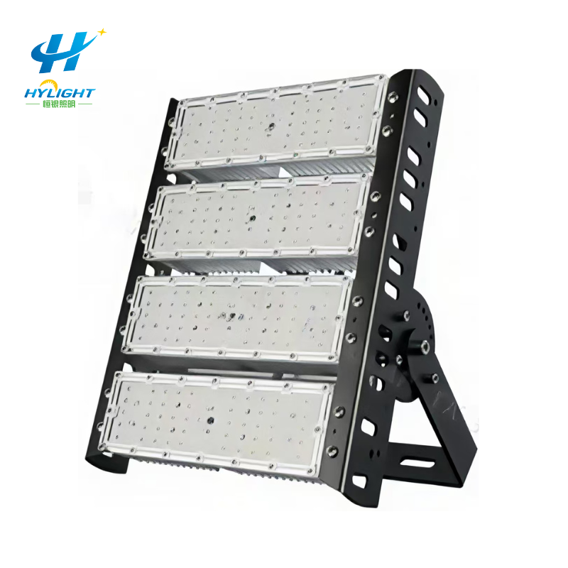
An LED flood light project can match the approved wattage schedule and still fail operationally. Aiming may have shifted during installation. A broad beam may brighten a boundary while leaving a work face underlit. One circuit may place an entire loading lane in darkness after a trip. Operators may bypass controls because the zones do not match real working patterns. A high average illuminance can coexist with glare, deep shadows, light trespass, or weak vertical visibility.
These problems are common in container yards, ports, logistics areas, industrial compounds, parking areas, security perimeters, construction sites, sports facilities, and large outdoor work zones because the installed result depends on the complete system: site geometry, tasks, mounting structures, optics, aiming coordinates, electrical distribution, controls, surface reflectance, obstructions, and field adjustment.
This guide gives contractors, EPC teams, consultants, distributors, and owners a commissioning method that turns the lighting design into a traceable aiming schedule, zone test, measurement record, defect process, and handover package.
GEO Summary
- Commission an LED flood light installation against the approved operational zones, lighting criteria, calculation model, luminaire schedule, aiming schedule, electrical single-line, controls narrative, and field-measurement plan—not against wattage alone.
- Give every floodlight a unique ID and record its pole or structure, mounting height, bracket orientation, optic, lumen package, CCT, driver/control type, circuit, control group, target point, tilt/rotation, shielding, and approved photometric-file revision.
- Check glare and spill from real observer positions: drivers, equipment operators, pedestrians, guards, neighbors, cameras, control rooms, waterways, roads, and site boundaries as applicable.
- Use the lowest output that meets the approved task and safety criteria. More light can reduce visibility when it creates glare, harsh contrast, veiling reflections, or deep shadows.
- Divide the electrical system into operationally meaningful zones. A single protective-device or contactor trip should not remove all useful light from a critical route unless the risk assessment explicitly accepts that outcome.
- Complete mechanical, electrical, controls, and aiming checks in daylight before night testing. Night commissioning should then verify output, uniformity, boundary conditions, controls, emergency or fallback behavior, and actual task visibility.
- Record measurement grid points, instrument, calibration status, weather, supply conditions, mounting state, control state, nearby light sources, surface conditions, and deviations from the design model.
- Lock final bracket settings, update as-built angles and target coordinates, photograph each luminaire, back up control settings, and retain the final calculation and field results under one revision-controlled handover package.
- For a project-specific proposal, send Henlyte the site drawing or model, task zones, criteria, mounting positions and heights, supply system, control needs, environmental conditions, quantity, destination, and required acceptance evidence.
The Short Answer: What Proves a Floodlight Installation Is Ready?
A project is ready for handover when it can prove all of the following:
- Installed products, optics, drivers, controls, accessories, and mounting arrangements match the approved submittal.
- Every luminaire is aimed at its approved target and the as-built aiming data is recorded.
- Mechanical supports, fasteners, brackets, safety restraints, cables, glands, and enclosures are complete and suitable for the site.
- Circuits and control groups match the approved operational zoning and labels.
- Field measurements meet the project criteria using the approved method.
- Glare, spill, reflections, shadows, and camera performance have been reviewed from relevant positions.
- Switching, dimming, scheduling, sensors, communications, alarms, and defined fallback modes operate correctly.
- Defects and design deviations are closed or formally accepted, and the owner receives reproducible settings and records.
A nighttime photograph that looks bright is not acceptance evidence. It does not state where the light falls, which control state was active, how the result was measured, or whether the same installation creates an unacceptable condition outside the photograph.
Translate Site Operations Into Lighting Zones
Start with what people and equipment do, not with a grid of identical luminaires. Map the actual site:
- Vehicle routes, turning areas, intersections, ramps, gates, and checkpoints
- Loading, unloading, lifting, inspection, storage, maintenance, and coupling areas
- Pedestrian routes, stairs, crossings, muster points, and entrances
- Security perimeters, fence lines, cameras, guard positions, and access control
- Water edges, neighboring property, public roads, residences, wildlife-sensitive areas, and other boundaries
- Areas that operate continuously, intermittently, seasonally, or only during an incident
- Tasks requiring vertical, directional, color, or detail visibility rather than horizontal illumination alone
For each zone, state the applicable project or local criteria, operating hours, control mode, priority, observer positions, and acceptable outage consequence. Do not invent one universal lux target. The correct requirement depends on the task, risk assessment, governing documents, and authority having jurisdiction.
Henlyte’s LED flood light range can establish available product directions, while the approved lighting design must establish the required optics, output, mounting, and controls for each zone.
Freeze the Photometric and Product Submittal
The calculation is useful only when it represents the equipment that will be installed. Control the relationship between model number, photometric file, optic, lumen output, driver current, CCT, mounting, tilt, and maintenance assumptions.
The approved package should include:
- Site plan or model with calculation surfaces, boundaries, obstructions, and observer locations
- Luminaire schedule with exact model, optic, output, CCT, CRI where relevant, driver, voltage, control option, and accessories
- Manufacturer photometric files tied to the offered configuration
- Calculation report with software/version, grid, mounting heights, aiming, reflectance, maintenance factor, and control state
- Point-by-point results and summary values required by the project
- Glare, spill, vertical illuminance, or other specialist calculations where applicable
- Pole, mast, bracket, platform, and structural interface data
- Electrical load schedule, single-line, protection, cable, earthing/bonding, and controls documents
- A variation process for substitutions or field changes
A product such as Henlyte’s 300 W adjustable-angle LED flood light is only a starting point. The project still needs the exact offered optical and electrical configuration plus a calculation based on the real geometry.
Create a Luminaire-by-Luminaire Aiming Schedule
The aiming schedule is the bridge between design and installation. “Aim toward the yard” is not repeatable.
| Aiming-schedule field | Why it matters |
|---|---|
| Luminaire ID | Links the drawing, circuit, product, photograph, test, fault, and asset register |
| Mounting location | Identifies pole, mast, building, platform, or bracket position |
| Mounting height and offset | Confirms the geometry used in the calculation |
| Model and optic | Prevents a visually similar but different distribution from being installed |
| Target coordinate or point | Gives the installer a reproducible direction in plan and elevation |
| Tilt and rotation convention | Avoids sign, reference-plane, or zero-position confusion |
| Bracket orientation | Records over-slung, under-slung, horizontal, vertical, or project-specific mounting |
| Shield or louver | Controls spill or glare and must match the calculation |
| Circuit and control group | Supports zoning tests and safe isolation |
| Final field setting | Records the accepted as-built adjustment rather than only the design value |
Use a consistent angle convention and show it graphically. A positive tilt measured from horizontal is not the same as an angle measured from vertical or from the bracket face. When field access is difficult, a target coordinate visible from the installation position may be more reliable than a small engraved scale.
Control Changes to Aiming
Do not allow unrecorded “fine tuning” across many luminaires. A change that improves one test point can create a boundary spill or uniformity problem elsewhere. Record each adjustment, reason, old and new setting, and the zones affected. Update the calculation if the deviation is material to acceptance.
Manage Glare, Spill and Reflections as Design Outcomes
Glare is not solved by lowering a single wattage number. It depends on luminous intensity toward the observer, apparent source size, adaptation, background, mounting position, angle, distance, and the observer’s task. Spill and reflected light can also create complaints or safety problems even when the light source is outside the direct view.
Review relevant viewpoints, including:
- Drivers approaching gates, curves, ramps, junctions, or loading areas
- Crane, forklift, reach-stacker, and other equipment operators at normal eye positions
- Pedestrians approaching stairs, crossings, or security points
- Guards and control-room staff viewing the site directly or through glazing
- CCTV cameras looking toward or near luminaires, reflective containers, wet pavement, or vehicle lights
- Adjacent roads, properties, residences, waterways, habitat, and the site boundary
Mitigation options can include a different optic, lower or redistributed output, revised mounting position, lower tilt, asymmetric distribution, shield, visor, louver, additional lower-output luminaires, control schedule, or a different target. The selected option should be recalculated and then verified in the field.
Good outdoor lighting directs light to the necessary task, uses only the required level, and applies controls when full output is not needed. That approach can improve visual conditions while reducing energy, spill, and sky glow.
Design Electrical Zones Around Operations and Failure Consequences
Electrical zoning is not just a panelboard exercise. It determines which work areas remain usable after a trip, maintenance isolation, communications failure, or control-system fault.
Ask the electrical designer to show:
- Which luminaires belong to each distribution circuit, contactor, relay, and control group
- How phases are balanced and how simultaneous inrush is managed
- Protective-device ratings and coordination for the actual drivers and cable system
- Surge-protection strategy and the interface with earthing/bonding
- Local isolation, lockout/tagout, and safe access provisions
- Manual override and the state after power loss or communications failure
- Dimming or scheduling commands and any default/fallback output
- Metering or monitoring points used during commissioning and operation
- Separation or redundancy for critical routes where required by the risk assessment
Avoid placing every luminaire serving a critical gate, route, or work face on one circuit merely because the connected load fits. Conversely, too many small circuits can increase panels, controls, cables, and maintenance complexity. The approved design should state the consequence being controlled.
Verify Driver and Control Compatibility
The same luminaire family may have different driver, dimming, voltage, surge, and inrush characteristics. Confirm the exact configuration. Test control behavior at full output, reduced output, switching transitions, restart, communications loss, and any scheduled modes.
If a remote driver is used, record its enclosure, distance, cable, voltage-drop basis, identification, accessibility, and relationship to the luminaire. If a local driver is used, confirm ambient-temperature and enclosure conditions at the installed position.
Check Mechanical and Environmental Interfaces
The light pole range and high mast light pole range illustrate structural directions, but the supplied mounting system must be reviewed for the exact floodlights and site.
Before energization, verify:
- Pole, mast, platform, building, bracket, and foundation correspond to approved drawings
- Luminaire quantity, mass, projected area, eccentricity, arrangement, and maintenance load are included in the structural review
- Brackets, bolts, locking devices, safety chains or restraints, and torque requirements are complete
- Aiming movement does not exceed the approved mechanical range or obstruct another luminaire
- Cable entry, bend radius, strain relief, drip control, glands, seals, and terminal access are correct
- Dissimilar-metal, coating, salt, chemical, dust, vibration, and temperature conditions are addressed
- Doors, driver boxes, junction boxes, and isolators remain safely accessible
- Luminaires cannot rotate or settle after aiming under normal wind and vibration conditions
A witness mark can help reveal later movement, but it does not replace the approved locking method or torque record.
Complete Daylight Pre-Commissioning
Daylight work reduces night-time troubleshooting and access risk.
- Reconcile installed quantities, IDs, model numbers, optics, drivers, controls, and accessories with the approved schedule.
- Inspect mounting, fasteners, safety restraints, cable routing, glands, enclosures, labels, and environmental protection.
- Verify electrical test records, protective devices, phase allocation, earthing/bonding, isolation, and circuit labels as applicable.
- Confirm control addresses, groups, schedules, scenes, sensor inputs, manual overrides, alarms, and fallback states.
- Set each luminaire to its approved target using the defined angle convention or coordinate method.
- Photograph the luminaire, bracket scale or aiming reference, target direction, label, and relevant cable/driver details.
- Record deviations and close them before night testing unless the commissioning authority accepts a controlled exception.
For raising-and-lowering systems, integrate these checks with the controlled operating and safety process described in Henlyte’s high mast raising and lowering FAT checklist.
Run Night Commissioning in a Controlled Sequence
Night testing should reproduce defined operating states and avoid changing several variables at once.
Step 1: Establish Test Conditions
Record date, time, weather, wet or dry surfaces, ambient conditions, nearby lighting, traffic or operational constraints, supply voltage, control scene, and any temporary obstruction. Confirm that construction lighting or vehicle headlights will not invalidate readings.
Step 2: Functional and Zone Test
Operate each circuit and control group independently. Confirm that IDs, panel labels, drawings, software groups, and actual luminaires agree. Test full output, scheduled reduction, manual override, restart, communications loss, and alarm behavior as required.
Step 3: Confirm Aiming and Visual Conditions
View the installation from defined observer positions. Look for visible sources, reflected glare, bright façades or containers, dark approaches, strong shadows, light beyond the target, and camera flare. Document observations rather than relying on memory.
Step 4: Measure the Approved Grid
Use the project measurement method and a suitable calibrated instrument. Record each point, not only the average. Where relevant, include horizontal and vertical planes, boundary points, task faces, camera targets, or other criteria stated in the design.
Step 5: Diagnose Deviations
Do not immediately increase output. Check luminaire ID, optic, aiming, mounting height, obstruction, control state, supply, surface condition, instrument position, and model assumptions. Adjust one controlled variable and record the result.
Step 6: Repeat Affected Checks
An aiming or output change can affect several zones and boundaries. Repeat the affected grid, observer, glare, spill, control, and electrical checks—not just the failed point.
Record Measurements So They Can Be Repeated
The field report should state:
- Drawing and calculation revision
- Luminaire schedule and control scene used
- Grid coordinates, point numbering, plane, height, and orientation
- Instrument manufacturer/model, serial number, calibration status, and range
- Date, time, weather, surface condition, and nearby light sources
- Supply condition and output/dimming state
- Measured results, required criteria, pass/fail status, and notes
- Aiming or control adjustments made during the test
- Photographs or marked plans showing test positions
- Open defects, responsible party, retest requirement, and closure approval
Average illuminance alone can hide weak points or severe peaks. Preserve the point-by-point data and any required uniformity, vertical, glare, boundary, or operational criteria.
Integrate Cameras and Human Tasks
Security projects should test both the human view and the camera system. A camera may struggle with a bright luminaire in-frame, reflective safety clothing, wet pavement, glossy vehicles, stacked containers, or rapid movement between dark and bright zones.
Test representative scenes, including:
- Person and vehicle approach directions
- Identification or observation zones defined by the security design
- Moving equipment and reflective surfaces
- Night-to-day or scene transitions where controls change
- Camera exposure, focus, infrared behavior, and image noise as applicable
- Power or communications fallback conditions
Do not claim a security outcome from illuminance alone. Camera specification, lens, mounting, compression, settings, maintenance, and the threat model all matter.
Close Out With an As-Built Handover Package
The owner should receive:
- Final site layout, calculation, luminaire schedule, and aiming schedule under one revision
- Product datasheets, photometric files, certificates, installation instructions, and warranty documents
- Pole/mast/bracket/foundation drawings and structural approvals
- Electrical single-line, panel/circuit schedules, cable data, protection, and earthing/bonding records
- Controls narrative, addresses/groups, schedules, scenes, passwords under the owner’s security process, and settings backup
- Mechanical, electrical, functional, aiming, and field-measurement test records
- Photographs linked to each luminaire ID
- Defect, deviation, adjustment, retest, and approval history
- Asset register, spare-parts list, preventive-maintenance plan, and training records
Henlyte’s earlier LED flood light photometric submittal checklist can be used before production; this commissioning guide completes the chain by checking the installed result.
FAQ
What is the correct aiming angle for an LED flood light?
There is no universal angle. It depends on mounting position, target geometry, optic, output, observer locations, glare and spill limits, and the approved calculation. Record a target coordinate and a clear angle convention so the setting can be reproduced.
Can field commissioning rely on average lux alone?
No. Average illuminance can hide dark points, excessive peaks, poor uniformity, glare, spill, weak vertical visibility, shadows, or camera problems. Use the complete project criteria and preserve point-by-point results.
How can glare from industrial floodlights be reduced?
Options include revising the optic, output, mounting position, tilt, target, shielding, louver, or luminaire layout. Review the result from relevant operator, driver, pedestrian, camera, and boundary positions and recalculate material changes.
Why divide floodlights into electrical and control zones?
Zones let the site match lighting to operations, isolate equipment safely, reduce unnecessary energy use, and control the consequence of a circuit or control failure. The zoning should follow the risk assessment rather than connected load alone.
When should an aiming change be accepted in the field?
Accept it only when the change is recorded, its effect on all relevant zones and boundaries is checked, material design deviations are recalculated, affected measurements are repeated, and the authorized commissioning party approves the as-built setting.
What information should a floodlight commissioning report contain?
Include the approved revisions, luminaire and control state, grid and observer positions, instrument/calibration, weather and surface conditions, point results, glare/spill observations, electrical and controls tests, adjustments, photographs, defects, retests, and final approval.
Request a Commissioning-Ready LED Flood Light Proposal
Planning a port, container yard, logistics hub, industrial compound, parking area, security perimeter, construction site, or sports facility? Send Henlyte the site drawing or model, task zones, project criteria, observer and boundary positions, mounting structures and heights, supply system, control philosophy, environmental conditions, quantity, destination, and required test format. Use the Henlyte inquiry page and include “LED flood light commissioning plan” so the team can identify missing inputs and prepare a traceable configuration proposal.